Bypass Switches & TAPs
BSTE-Series Bypass Switch
Silicom Managed Bypass Switch Specifications
Silicom Managed Bypass Switch is designed for Gigabit Ethernet networks. The Silicom managed Bypass switch is targeted to maintain network connectivity when the in-line system fails. The Managed Bypass switch is based on a reliable passive switch, console management port and on board watch dog timer controller.
Silicom Managed Bypass switch supports three modes of operations: Normal, Bypass and Disconnect modes. . In Normal modes, the Bypass switch diverts the network traffic to attached in-line network system. In Bypass mode, the inline traffic is diverted to the network link and no longer routed to the in-line device. In Disconnect mode, the switch simulates switch / rout cable disconnection. The Managed Bypass Switch can be programmed to Bypass or disconnect its Ethernet ports on event of power fail, Link fail or user request.
The Silicom Managed Bypass switch includes an on board Watchdog timer controller (WDT) and a passive switch. The on board WDT controller can receive heartbeat “alive” packet via its serial communication console, USB, or its Ethernet port (selected models).
The Silicom Managed Bypass switch can be shipped as a stand alone unit (BSS) or as a rack mount 1U host system (BS1U). The rack mount 1U host system support up to four Bypass modules. Each Bypass module supports a Bypass segment. The Bypass modules in the 1U host system can be chained in order to enable multi-Bypass segment to support systems with limited management accessibility.
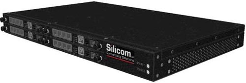
Stand Alone unit
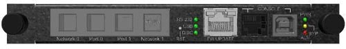
The Silicom Managed Bypass switch a stand-alone flavor includes four Gigabit Ethernet data ports. Console management includes Serial (RJ11), USB and Ethernet port (selected models). The stand-alone flavor includes an external +12V power supply.
Figure: 1- Front panel view of BSSF-CEM
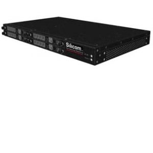
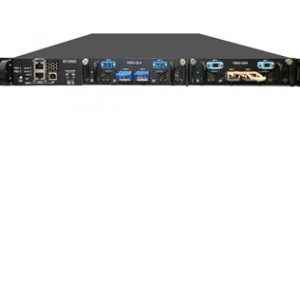
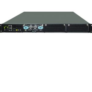
1U Rack mount host system
The 1U host system supports up to four Bypass Switch modules. The Bypass switch host includes two redundant internal dual 110 – 220 V AC power supplies.
The Silicom Managed Bypass switch host supports two types of Bypass switch modules, a controller (-C) and a slave (-S). The controller Bypass switch (-C) module includes data ports and management ports. The slave module includes data ports only. The controller Bypass module ( -C) and the slave Bypass module can be chained 1U host system. The chain of modules was designed in order support systems with limited management accessibility that requires multi-Bypass segment configurations.
Figure: 2 – Front panel view of BS1U with four BST-CE
BSTE-Series Bypass Switch
Silicom Managed Bypass Switch Specifications
Bypass
- Bypass Ethernet ports on Power Fail, System Hangs, management port fail, Software Application Hangs or user request
- Disconnect ports on Power Fail, System Hangs or Software Application Hangs
- Software programmable Bypass or Normal or Disconnect Mode
- On Board Watch Dog Timer (WDT) Controller
- Software programmable time out interval
- Software Programmable WDT Enable / Disable counter
- Software programmable Bypass Capability Enable / Disable: Can be also in Normal mode at power off
- Built-in Bypass circuitry, which operates in host system fails, Power OFF and programmable software
- Programmable state (Bypass mode or Normal mode or Disconnect mode) at switch and host Power up
- Programmable state (Bypass mode or Normal mode) at switch and host Power up, switch and host power off
- Independent Bypass / Disconnect / Normal operation in every module
- Reliable passive switch architecture
- Chained configuration: enable multi-Bypass segment to support systems with limited management accessibility
Copper Gigabit Ethernet 1000Base-T
- Supports Gigabit Ethernet (1000Base-T), Fast Ethernet (100Base-Tx) and Ethernet (10Base-T)
- RJ-45 female connectors
Bypass Switch 1U Host switch (BS1U)
- Enable chaining modules – one console can control several slave modules in the system
- 1U mechanical specification
- Dual internal 110 – 220V AC Power supply for redundancy
BSTE-Series Bypass Switch
Silicom Managed Bypass Switch Specifications
Copper Gigabit Ethernet Technical Specifications - (1000Base-T) Adapters | |
| IEEE Standard / Network topology | Gigabit Ethernet, 1000Base-T Fast Ethernet, 100Base-TX Ethernet, 10Base-T |
| Data Transfer Rate | 1000 Mbit/s, 100 Mbit/s and 10 Mbits/sec in simplex mode per port 2000Mbit/s 200 and 20 Mbit/s in full duplex mode per port |
| Cables and Operating distance | 10Base-T Category 3, 4, or 5 maximum 50m * 100Base-Tx Category 5 maximum 50m * 1000Base-T Category 5E maximum 50m * *Theoretical Distance – Defined as half a distance as stated by the IEEE 802.3 standard |
Bypass Specifications | |
| WDT Interval (Software Programmable) | 3,276,800 mSec (3,276.8 Sec): Maximum 100 mSec ( 0.1 Sec) : Minimum WDT Interval = (2^wdt_interval_parameter)*(0.1) sec. wdt_interval_parameter: { Valid Range: 0-15} |
BSST-CE: Bypass Switch stand alone controller | |
| Size | x 152mm x 120.5mm x 24mm (6" x 4.75" x 1") Wide x Depth X Height |
| Voltage | +12V (Min 11.4, Max, 12.6V) |
| Operating Humidity | 0%–90%, non-condensing |
| Operating Temperature | 0°C – 50°C (32°F - 122°F) |
| Storage Temperature | -20°C–65°C (-4°F–149°F) |
| EMC Certifications | Class B |
BSST-CE: LED and Connector Specifications | |
| LEDs | (8) LED Power (Green) Bypass (Yellow) Alarm (Red) Console Serial Link (Green) Console USB Link (Green) Disconnect (Yellow) Console/Program Ethernet Link (100M Green, 10M Yellow) Console/Program Ethernet Act (Green on RJ11 console) |
| Connectors | (4) Shielded RJ-45 (1) RJ11 console (1) USB console (1) RJ45 console |
BS1U: Bypass Switch 1U Host system | |
| Dockings | Front holders 1U rack mount |
| Voltage Input | AC: 90-240 VAC Auto-Select |
| Size | 444mm x 270 mm x 44 mm ( 17.48” x 10.63” x 1.732”) Wide x Depth X Height |
| Operating Humidity | 0%–90%, non-condensing |
| Operating Temperature | 0°C – 50°C (32°F - 122°F) |
| Storage Temperature | -20°C–65°C (-4°F–149°F) |
| EMC Certifications | Class B |
| MTBF* | 1375 years (BS1U only) * The prediction was performed for 40°C Ambient temperature, GB Environmental condition. The reliability prediction was performed in accordance with Telcordia SR-332 |
BST-CE: 1U module Controller | |
| Size | 129mm x 100mm (7.709" x 3.937") |
| Voltage | +12V (Min 11.4, Max, 12.6V) |
| Operating Humidity | 0%–90%, non-condensing |
| Operating Temperature | 0°C – 50°C (32°F - 122°F) |
| Storage Temperature | -20°C–65°C (-4°F–149°F) |
| EMC Certifications: | Class B |
BST-CE: LED and Connector Specifications | |
| LEDs: | (8) LED Power (Green) Bypass (Yellow) Alarm (Red) Console Serial Link (Green) Console USB Link (Green) Disconnect (Yellow) Console/Program Ethernet Link (100M Green, 10M Yellow) Console/Program Ethernet Act (Green on RJ11 console) |
| Connectors | (4) Shielded RJ-45 (1) RJ11 console (1) USB console (1) RJ45 console |
BST-SE: 1U module Slave Multi-Mode and Single Mode | |
| Size | 129mm x 100mm (7.709" x 3.937") |
| Voltage | +12V (Min 11.4, Max, 12.6V) |
| Operating Humidity | 0%–90%, non-condensing |
| Operating Temperature | 0°C – 50°C (32°F - 122°F) |
| Storage Temperature | -20°C–65°C (-4°F–149°F) |
| EMC Certifications | Class B |
| MTBF* | 315 years * The prediction was performed for 40°C Ambient temperature, GB Environmental condition. The reliability prediction was performed in accordance with Telcordia SR-332 |
BST-SE: LED and Connector Specifications | |
| LEDs | (6) LED Power (Green) Bypass (Yellow) Alarm (Red) Disconnect (Yellow) Program Ethernet Link (100M Green, 10M Yellow) Program Ethernet Act (Green on RJ11 console) |
| Connectors | (4) Shielded RJ-45 (1) RJ45 console |
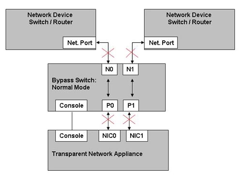
Functional Description
Figure: 3 - Normal Mode Functional Block Diagram
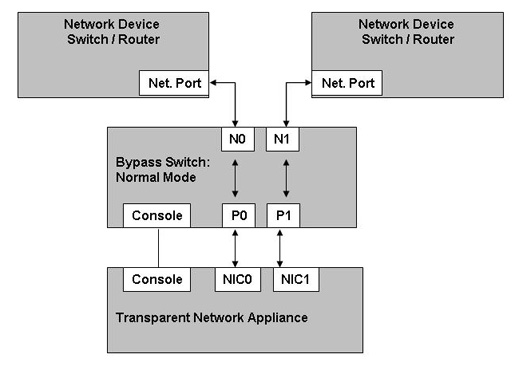
Figure: 4 - Bypass Mode Functional Block Diagram
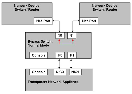
Figure: 5 – Disconnect Mode Functional Block Diagram
BSTE-Series Bypass Switch
Silicom Managed Bypass Switch Specifications
P/N | System Format | Media | Console Port | Media Type | -XY-XY-XY | Power Cord | -R |
| BS: Managed Bypass Switch | 1U: 1U S: Stand Alone | F: Fiber T: Copper | -SE: Slave -CE: Controller w/Ethernet | M: Multimode S: Single mode T: Copper | For additional modules console port and media type: X: C / S / CE Y: M/S/T | -US -EU -CN -48 | ROHS |
Stand Alone
P/N | Description | Notes |
| BSST-CE-US-R | Gigabit Copper Managed Bypass switch | Stand alone, controller Copper, w/ US style power cable, Ethernet, serial and USB management cables. |
| BSST-CE-EU-R | Gigabit Copper Managed Bypass switch | Stand alone, controller Copper, w/ EU style power cable, Ethernet, serial and USB management cables |
| BSST-CE-CN-R | Gigabit Copper Managed Bypass switch | Stand alone, controller Copper, w/ CN style power cable, Ethernet, serial and USB management cables. |
| RK-1U-2-BSS | 1U Rack Mount Kit for two BSS products |
1U Host System
P/N | Description | Notes |
| BS1U-CET-US-R | 1U w/ Gigabit Copper Managed Bypass Switch | 1U host with one controller Copper, w/ US style power cable, Ethernet, serial and USB management cables. |
| BS1U-CET-EU-R | 1U w/ Gigabit Copper Managed Bypass Switch | 1U host with one controller Copper, EU style power cable, Ethernet, serial and USB management cables |
| BS1U-CET-ST-CN-R | 1U w/ Gigabit Copper Managed Bypass Switch | 1U host with one controller and one slave Copper, CN style power cable, Ethernet, serial and USB management cables. |
| BS1U-CET-CT-CN-R | 1U w/ Gigabit Copper Managed Bypass Switch | 1U host with 2 controllers Copper, CN style power cable, Ethernet, serial and USB management cables. |
| BS1U-US-RoHS | Bypass Switch 1U Host System | 1U host system w/ US style power cable. |
| BS1U-EU-RoHS | Bypass Switch 1U Host System | 1U host system w / EU style power cable. |
| BS1U-CN-RoHS | Bypass Switch 1U Host System | 1U host system w / CN style power cable. |
| BS1U-48-RoHS | Bypass Switch 1U Host System | 1U host system w / -48V redundant power supply |
| BST-CE-R | Gigabit Copper Managed Bypass switch | Add-in module, controller Copper, w/ , Ethernet serial and USB management cables. |
| BST-SE-R | Gigabit Copper Managed Bypass switch | Add-in module, slave Copper, w/ serial , Ethernet and USB management cables. |
Note: Model P/N
--US: Includes US power cable (90-240 VAC Auto-Select)
-EU: Includes EU power cable (90-240 VAC Auto-Select)
-CN: Includes CN power cable (90-240 VAC Auto-Select)
-48: (-75 - -36) VDC
1V4